ZeroHack
All in One Hacking System Like Flipper Zero
Required Components
- ESP32 Dev Board (e.g., ESP32-WROOM-32 or ESP32-WROVER)
- IR LED (for IR Blaster)
- 433MHz RF Transmitter & Receiver
- NFC Module (e.g., PN532 via I2C/SPI)
- Wi-Fi Module (built-in in ESP32)
- Bluetooth LE (built-in in ESP32)
- 125kHz RFID Module (e.g., RFID-RC522)
- iButton Reader Module
- SubGHz Transceiver (e.g., CC1101)
- GPIO Pins / Breadboard / Jumper wires
- USB OTG Cable (for power + serial communication)
- Battery or USB power supply
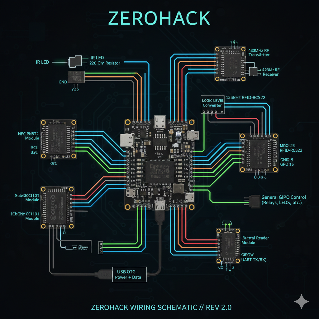
Wiring Diagram Summary
- IR LED — GPIO 23 (with 220Ω resistor)
- RF 433 MHz TX — GPIO 17
- RF 433 MHz RX — GPIO 16
- NFC Module (PN532) — I2C: GPIO 21 (SDA), GPIO 22 (SCL)
- RFID-RC522 — SPI: MOSI (GPIO 23), MISO (GPIO 19), SCK (GPIO 18), SDA (GPIO 5)
- SubGHz CC1101 — SPI: MOSI (GPIO 23), MISO (GPIO 19), SCK (GPIO 18), CSN (GPIO 15)
- iButton Module — GPIO 13
Power Supply & Communication
- ESP32 powered via USB OTG from the Android app (ZeroHack)
- Communication: USB Serial, Bluetooth, or WiFi (TCP Socket or HTTP)
Android App (ZeroHack) Modules
- IR Blast
- RF Send
- NFC Ping
- WiFi Jam & Deauth
- GPIO Control
- BadUSB Emulation
- RFID Emulation
- iButton Emulation
- SubGHz Scan
- Signal Replay
- Bluetooth Exploit
- UART Hacking
- Logic Analyzer
Firmware Flashing
- Use PlatformIO or Arduino IDE
- Select ESP32 Dev Board
- Upload custom firmware (.ino or .bin) for each module
- Configure UART or BLE/WiFi communication for mobile control
ESP32 Components Connection
[ESP32 BOARD]
|-- GPIO 17 ------> IR Transmitter (OUT)
|-- GPIO 16 ------> RF Transmitter (DATA)
|-- GPIO 15 <------ RF Receiver (DATA)
|-- GPIO 21 <--> NFC Module (SDA)
|-- GPIO 22 ------> NFC Module (SCL)
|-- GPIO 23 ------> CC1101 SubGHz (SI)
|-- GPIO 19 <------ CC1101 SubGHz (SO)
|-- GPIO 18 ------> CC1101 SubGHz (SCK)
|-- GPIO 5 ------> CC1101 SubGHz (CSN)
|-- GPIO 13 ------> RFID Module (SDA)
|-- GPIO 12 ------> iButton Probe
|-- GPIO 25 <--> UART TX
|-- GPIO 26 <--> UART RX
|-- GPIO 32 ------> WiFi Jammer Antenna
|-- GPIO 33 ------> Bluetooth Module (for external amp/hack)
|-- GPIOs 2, 4, 27 --> General GPIO Control (Relays, LEDs, etc.)
GND -------------> All Modules' GND
3V3 or 5V -------> VCC depending on module requirement
Circuit Diagram
Future Expandability
- Modular firmware system for additional hacking tools
- OTA updates via ZeroHack App
- Expandable Bluetooth device scanner/sniffer
- File-based scripting system (BadUSB, replay scripts)
Application Source
Download ZipFirmware Source
Download ZipCopyRight
Humayun Shahriar Himu